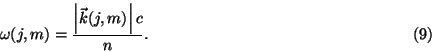
1. Introduction
The velocity of a light pulse in a dielectric medium without dispersion is given by the speed of light in that medium. However, at the boundaries of such media some interesting effects occur especially under conditions of total reflection. If the boundary at which total reflection occurs does not represent an infinitely extended barrier, partial tunneling through the barrier takes place. Experiments with multilayered mirrors and other barriers [1] which reflect almost all the light have shown that transmission of light appears to occur at superluminal speeds and that transmission speeds do not depend on the thickness of the barrier.
In this paper we discuss the effects for a special kind of barrier which is hit by a Gaussian pulse.
2. The arrangement of the barrier
As a barrier we define a slab of vacuum which separates two dielectric
media with a given refractive index n>1. The critical angle of incidence
is given by
Light pulses with an angle of incidence greater than this critical angle are almost completely reflected. However, there is a part of the electromagnetic field which can tunnel through the slab if its thickness is of the order of magnitude of the average wavelength of the pulse. It is this transmitted part of the pulse which we are interested in. Figure 1 outlines the arrangement of the boundary for the incoming pulse, resulting in a reflected and transmitted component.
![\includegraphics[width=9cm]{mul1.eps}](img4.gif)
3. The description of the pulse
For the sake of simplicity we take a Gaussian pulse as can be provided by a
mode-locked laser. For our investigation we define a two-dimensional
coordinate system in the plane of incidence (the x,z-plane in Fig. 1).
Let us first introduce the two unit vectors ![]() and
and ![]() ;
;
![]() being parallel to the propagation direction of the pulse,
being parallel to the propagation direction of the pulse,
![]() being perpendicular to
being perpendicular to ![]() . With the angle of incidence
. With the angle of incidence
![]() we obtain
we obtain
We choose the coordinate system in such a way that, at the time t=0, the
pulse maximum is located at the origin, i.e., the electric field at t=0
is given by
![\begin{displaymath}E(\vec{r}=a\vec{e}_1+b\vec{e}_2,t=0)=E_0\exp\left[-\frac{1}{2...
...ht)^2\right]\exp\left(-{\rm i}\vec{k}_0\vec{r}\right), \eqno(4)\end{displaymath}](img14.gif)
The integral (6) is the superposition of plane waves which propagate in
time. Thus, the complete description of the pulse in time and space is
obtained as
4. A plane wave at the barrier
We will now investigate what happens to a plane wave which hits the
barrier. ![]() denotes the wave vector,
denotes the wave vector, ![]() is the angle of
incidence. The plane wave can be written in the form
is the angle of
incidence. The plane wave can be written in the form
Let us examine what the evanescent wave looks like if the angle of
incidence ![]() is greater than the critical angle. We use (11) to get
an expression for
is greater than the critical angle. We use (11) to get
an expression for ![]()
The evanescent wave in the slab produces a transmitted wave at the second
boundary
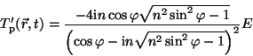
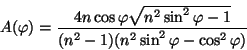
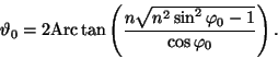
Let us transform the amplitude in (18):
![\begin{displaymath}\frac{-4{\rm i}n\cos\varphi\sqrt{n^2\sin^2\varphi-1}}{(\cos\v...
...){\rm e}^{{\rm i}[\vartheta(\varphi)-\frac{\pi}{2}]}, \eqno(19)\end{displaymath}](img47.gif)
5. The transmitted pulse
Let us return to the Gaussian pulse. In order to obtain the description of
the transmitted pulse we have to replace the expressions for the plane
waves in (8) by (21)
![\includegraphics[width=6cm]{mul2.eps}](img53.gif)
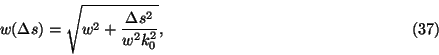
The dependence of ![]() is given by (see Fig. 2)
is given by (see Fig. 2)
In order to see the influence of the new terms in the exponential function
we need the following expansions:

For the real part we get the approximation
![\begin{displaymath}\qquad+{\rm i}\left[\vartheta_0+\frac{2n\sin\varphi_0}{(n^2\s...
...sqrt{n^2\sin^2\varphi_0-1}}\frac{m}{k_0}
-\frac{\pi}{2}\right]\end{displaymath}](img75.gif)

Let us find the maximum of the transmitted Gaussian wave packet at a
specific time t. In a homogeneous medium without dispersion the maximum
of a Gaussian pulse travels at a constant speed given by the vacuum speed
of light divided by the refractive index of the medium. Its amplitude
decays with time because of the diffraction of the pulse. After the pulse
travelled a distance ![]() , its width can be derived as
, its width can be derived as
The transmitted wave propagates in the direction of the new wave vector
![]() . The physical interpretation of this directional change is the
following. There are wave components of the incoming pulse that have
propagation directions which are more favorable for transmission through
the slab than along the main direction of the pulse. These preferentially
transmitted components decay less in the slab than the other components of
the pulse. These pulse components having the smaller angles of incidence
constitute the main part of the transmitted pulse. This explains why the
transmitted pulse leaves the slab under an angle slightly smaller than the
initial angle of incidence.
. The physical interpretation of this directional change is the
following. There are wave components of the incoming pulse that have
propagation directions which are more favorable for transmission through
the slab than along the main direction of the pulse. These preferentially
transmitted components decay less in the slab than the other components of
the pulse. These pulse components having the smaller angles of incidence
constitute the main part of the transmitted pulse. This explains why the
transmitted pulse leaves the slab under an angle slightly smaller than the
initial angle of incidence.
Where and when does the transmitted pulse occur on the opposite side of the
slab? Equation (32) describes the pulse after transmission through the
slab. By way of extrapolation to the time t=0, we may define a virtual
origin of the pulse, which is shifted by ![]() ,
, ![]() with
respect to the true origin (x=0, z=0). From this virtual origin and the
propagation vector we obtain the exit position (
with
respect to the true origin (x=0, z=0). From this virtual origin and the
propagation vector we obtain the exit position (![]() ,
,
![]() ) for the transmitted pulse
) for the transmitted pulse
Let us consider the tunneling time. There are some difficulties to define a
tunneling time. Experimentally it is not possible to detect directly the
time point when the pulse leaves the slab, but the pulse must be observed
somewhere in the adjacent medium behind the slab. The time needed by the
pulse to get from its origin to the point of detection can be measured. The
question is what we should compare it to. We could do the same experiment
without a slab. However, as we have seen the transmitted pulse has a
slightly different direction than the original pulse. Thus, an identical
but undisturbed pulse will not be detected at the same place as the
transmitted pulse. Thus, the two paths of the pulses cannot be directly
compared. It is much better to take as reference a pulse which travels
through the homogeneous medium with the same direction as the transmitted
pulse (see Fig. 3). In this case the two paths are parallel and differ only
in the small lateral shift caused by the slab. Let us define the tunneling
time as the difference between the time point when the maximum of the
transmitted pulse appears on the far side of the slab and the time point
when the undisturbed pulse hits the slab. This yields
![\includegraphics[width=9cm]{mul3.eps}](img108.gif)
Fig.3. The arrangement of the experiment to measure the time differences between tunneled and undisturbed pulses.
If we calculate the difference between the time needed by a pulse to reach
the detector (Fig. 3) either with or without a slab in between we obtain
![\begin{displaymath}\approx\frac{n}{c}\left[l\cos\varphi'_0+\frac{2n\tan\varphi_0...
...{n^2\sin^2\varphi_0-1}}\sin\varphi'
_0 \right]-t_{\rm tunnel},\end{displaymath}](img110.gif)
The question is whether these results violate causality. Apparently the tunneling time for the pulse maximum is superluminal. However, it must be emphasized that it is only the maximum which appears to travel at this speed. Actually the pulse is reshaped in the slab and comes out in a different form. Furthermore, the energy distribution of Gaussian pulses is not limited in space. Therefore, we cannot apply the principle of causality in its simplest form. Only if there was a distinct front of the pulse one could state that at any point no signal can be detected before the pulse front propagating with the vacuum speed of light would reach it.
6. Visualization of tunneling
![\includegraphics[width=13cm]{mul4.eps}](img112.gif)
![\includegraphics[width=13cm]{mul5.eps}](img113.gif)
Fig.5. Development of a pulse reflected at and transmitted through a barrier (viewed along the z-axis).
![\includegraphics[width=13cm]{mul6.eps}](img114.gif)
Fig.6. Development of a pulse reflected at and transmitted through a barrier (viewed along the x-axis).
The following pictures are not based on the above approximations, but take into account multiple pulse reflections. They show the development of a tunneling pulse in time. The first series (Fig. 4) gives an overview: the incident pulse approaches from behind (z<0, x>0). In the first picture (Fig. 4a) the pulse maximum is expected to be still in front of the slab which is located between z=0 and z=3. The z coordinate is scaled in units of vacuum wavelengths of the laser. As the pulse is very close to the slab, parts of the incident and reflected pulse interfere. This causes the disturbances and the high values of the amplitude in the vicinity of the slab. Actually one would find standing waves in front of the slab (z<0); however, this fine structure is not resolved. As can be seen, the field magnitude decreases very rapidly in the slab. The maximum of the transmitted pulse already appears in the second picture (Fig. 4b) when the calculated position of the maximum of the incident pulse has not yet reached the slab. The last two figures (Fig. 4c, d) show the further development. Apart from the transmitted Gaussian pulse we can see a second small pulse. Probably it is due to the multiple reflections or to higher order terms which we did not take into account in our approximations. The following two series (Fig. 5a-d and 6a-d) show the pulse at the same time points, but in views perpendicular to the z-axis and x-axis, respectively. In these views the two main effects related to tunneling are nicely born out. In the series of Fig. 5 the backward shift can be observed, whereas in the series of Fig. 6 the fact that tunneling occurs faster than reflection is evident. The maximum of the transmitted pulse already leaves the slab before the incident pulse hits the slab. In Fig. 6d, the transmitted pulse is farther away from the slab than the reflected one.
Acknowledgment
I would like to thank Prof. J. Mostowski (Polish Academy of Sciences, Warsaw) for introducing me to this problem. I am also very grateful to Dr. Ch. Fattinger (F. Hoffmann-LaRoche Ltd, Basel) for his interest and many helpful comments and discussions.